Kim • Published 06 2026 Aug
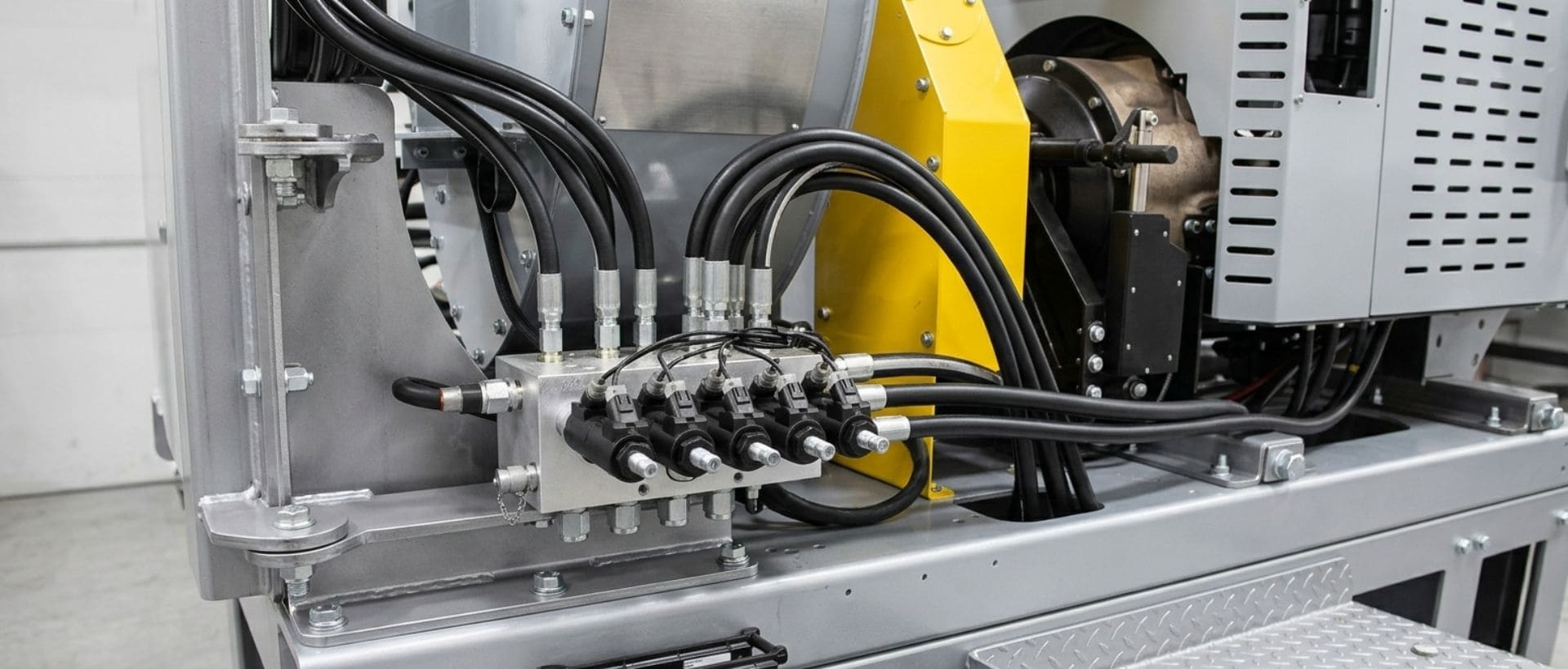
Precision deep hole drilling of automotive hydraulic manifolds is critical for creating precise internal channels for high-pressure systems. In this blog, we’ll explain the key methods, why accuracy is crucial, how everything works, and the usual issues engineers may face.
Drilling refers to the machining process whereby holes are created through the rotation of a cutting tool on the workpiece. In most cases, a deep hole is said to be created once the ratio of depth to diameter exceeds 10:1.
We use this deep hole drilling to create straight, deep holes in automotive hydraulic manifolds, which serve as fluid conduits for important vehicle components, including braking, steering, transmissions, and suspensions.
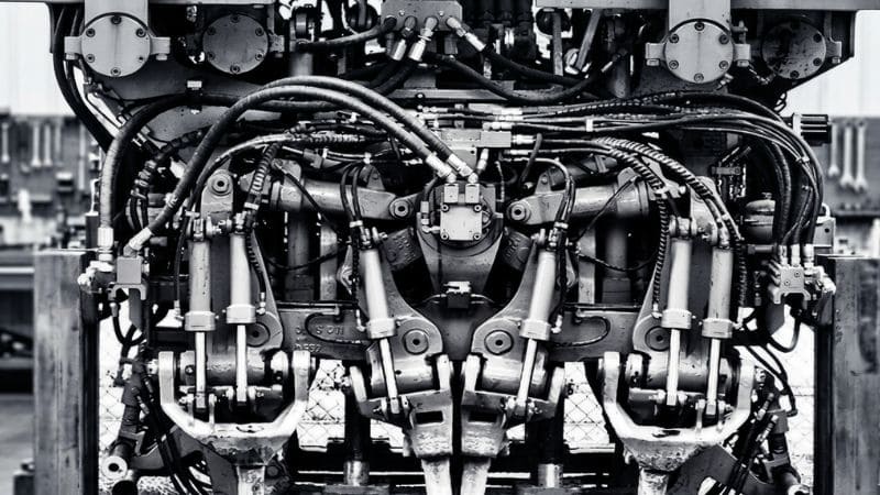
To ensure accurate flow passage performance, we machine every flow passage to exact sizes. This allows hydraulic fluid to flow easily and freely from passage to passage in the manifold.
It is important that we maintain close dimensional tolerances when deep hole drilling machine parts in order to create a secure seal on all surfaces in the manifold. Dimensionally accurate holes and mating surfaces will prevent leaks and avoid seal failures in the system.
Many times, hydraulic manifolds have multiple flow passages that may intersect. We carefully control burr formation during deep hole drilling to ensure proper hydraulic flow without contaminant issues.
Smooth bore geometry ensures that the pressure inside the manifold remains consistent throughout. Straight passages with consistent bore geometry are also less likely to develop stress points, ensuring efficient hydraulic performance during operation.
The efficiency of fluid flow increases when the internal surface is smooth, as this lowers friction and wear. Smooth internal surfaces also help ensure efficient sealing of hydraulic systems.
For related hydraulic performance-critical components, you can also explore how we optimize hydraulic cylinder heads through precision machining and tight tolerance control.
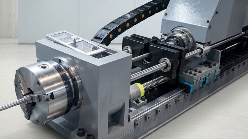
We use BTA drilling in cases where stability and productivity are essential for long and intensive processing. This technique is particularly effective when it comes to sturdy set-ups that provide support along the bore to minimize deflection when drilling.
BTA drillings also work effectively in manufacturing batches since they ensure constant operation throughout extended periods of processing. They are preferred when it comes to maintaining constant alignment within intersecting holes in hydraulic manifolds.
In cases where a high degree of accuracy of the position of the drill is necessary right from the start of the process, we use gun drilling. This process ensures a constant guided path when drilling, ensuring that deviation is minimized during the drilling of long holes.
One strength of this process is that it works effectively in thin and long workpieces. It also ensures excellent roundness, ensuring that it provides an excellent solution when it comes to precision sealing and metering in hydraulic systems.
| Feature | BTA Drilling | Gun Drilling |
| Diameter Range | 20–600 mm (0.8–24 in) | 2–32 mm (0.08–1.25 in) |
| Depth Capability | Up to 100× hole diameter | Up to 20× hole diameter |
| Chip Removal | Through the center of the drill tube | Through an external V-shaped groove |
| Coolant Flow | External to internal | Internal to external |
| Production Speed | Higher material removal rate for large holes | Better control and accuracy for small holes |
| Typical Applications | Hydraulic manifolds, engine blocks, and structural components | Valve bodies, fuel rails, and precision hydraulic passages |
The deep hole drilling process involves the spinning of the cutting tool as it advances through the material. In certain cases, the workpiece may spin. The tool feeds continuously till the desired depth of penetration is achieved.
First, we choose the appropriate tool according to the hole size, depth, and material. Next, we fix the workpiece securely and align it accurately so that the hole is drilled in its designated location.
Once the CNC machine initiates the process, the rotation of the tool or the workpiece, based on how it is set up, takes place at the preset speed.
We introduce high-pressure coolant into the cutting area to help eject the chips effectively and manage heat during the process.
The feeding of the tool into the work material takes place at a constant feed rate for optimal results.
In order to achieve a desirable level of precision when performing deep drilling operations, we will need to ensure proper control of certain critical machining conditions, such as:
Feed Rate Control and Spindle Speed Optimization: This involves precise regulation of both the cutting feed and spindle speeds. This balance will minimize any tool deflections that may occur.
High-Pressure Coolant Management: A stable delivery of coolant at high pressure will be maintained. This will allow us to evacuate chips from the cutting area effectively.
Tool Wear Monitoring and Chip Evacuation Stability: We will monitor tool wear and chip formation to prevent disruptions in the machining process.
Thermal Expansion Control: We shall manage heat generation to avoid thermal elongation of the machined parts.
Vibration Suppression: We will minimize vibration in order to minimize deviations in bore geometry.
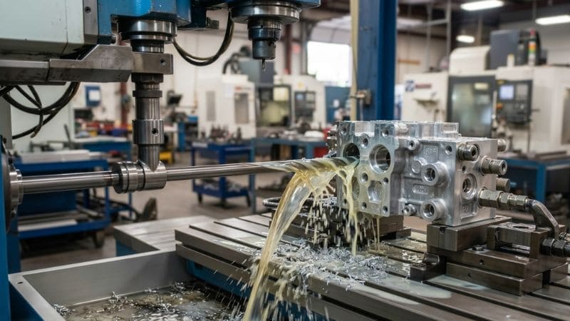
Based on our experience with hydraulic manifolds, deep hole drilling relies heavily on setup precision, process consistency, and material response.
Even a deviation of only 0.02 to 0.05 mm on the initial point of entry may amplify significantly as the depth of the hole increases. As per our observations, any deviation tends to occur beyond the length of 10x – 20x times the diameter of the hole.
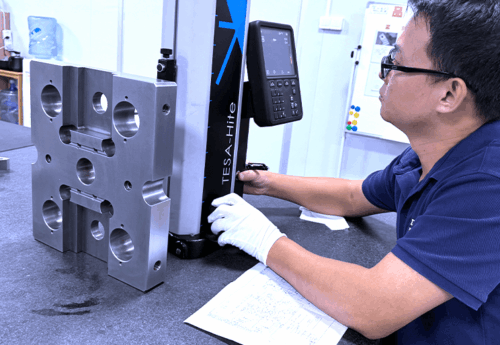
To address this issue, we perform laser-guided alignment prior to the actual process of drilling. Moreover, the straightness of the hole must be checked at the halfway stage in critical holes.
The cross-holes present in hydraulic manifolds will often have burrs that impede fluid flows through them. In fact, burrs, even with a diameter of around 0.1 mm, can create problems of contamination and sealing.
We prevent this problem by designing the end of tools to be optimal, in addition to adopting additional techniques like high-pressure flushing or secondary cutting.
Constant coolant pressure is crucial for effective deep drilling. If the pressure falls below our operational limit of 8-12 MPa, the chip removal may become poor and affect surface roughness.
We solve this problem by adopting a special system for delivering coolant under high pressures in combination with monitoring the pressure level. Stability tests for coolant flows precede long operations.
It is difficult to provide good surface quality throughout the entire length of the hole. Our goal is to achieve a surface roughness Ra 0.8-1.6 µm, but this is possible only under strict process control.
We stabilize surface finish by using wear-resistant cutting tools and careful regulation of feed rates. The inspection of tool condition during machining helps to prevent finish deterioration.
If thin walls of about 2-3 mm are present in the complex manifolds, then deformation may occur under high cutting loads.
We reduce this risk through optimized cutting processes, allowing for smaller radial cutting loads. Also, the use of gradual material removal and intermediate checks for stress relaxation is recommended.
From our experience, precision, rigidity, and process control are the keys to deep hole drilling for hydraulic manifolds. We have addressed issues such as tool deflection, burr formation, and coolant pressure variations, and more, continually fine-tuning our process.
At DEK Automotive, we use advanced drilling technologies and strict monitoring to ensure consistent quality across every part we produce. Contact us today for trusted, precision machining solutions.
Kim oversees engineering operations, including complex CNC programming, DFM reviews, and solving challenges associated with high-precision automotive components. He specializes in strict tolerance control and multi-axis machining of complex geometries essential for powertrain modules, suspension systems, and ADAS sensor housings. Outside of work, he enjoys the precision and strategy of playing snooker.
We integrate advanced machining, specialized materials, and surface finishing to deliver mission-critical parts that meet every rigorous automotive standard.
Fill out the form below and our team will get back to you promptly with a personalized quote tailored to your needs.