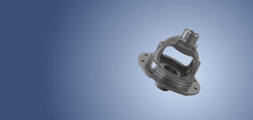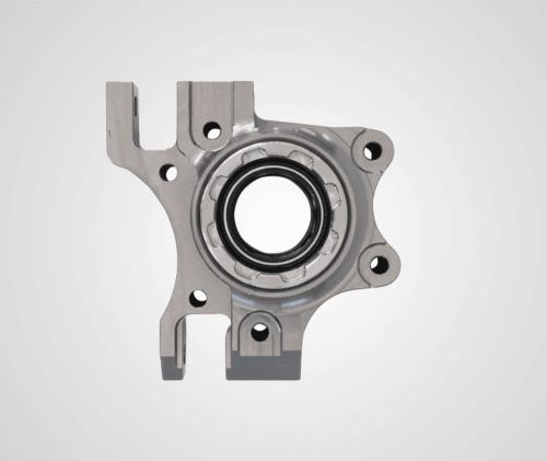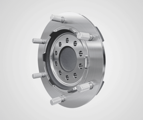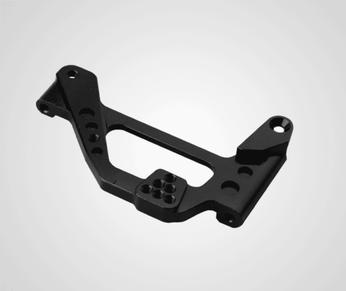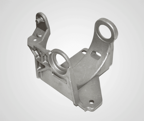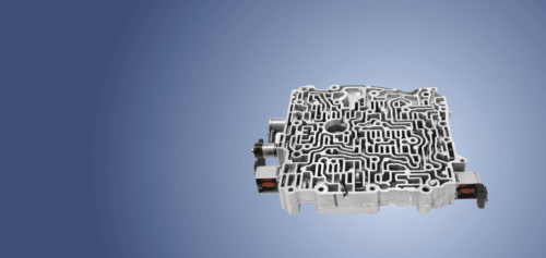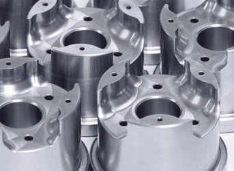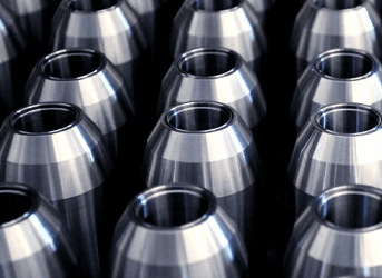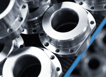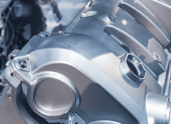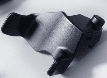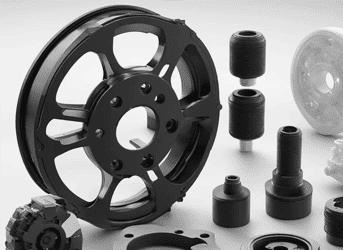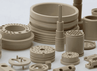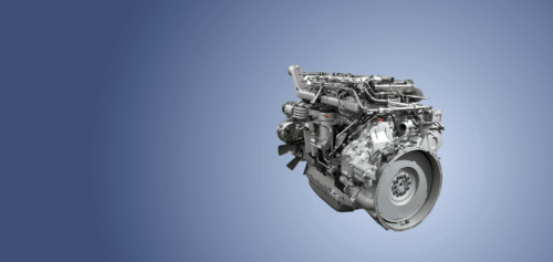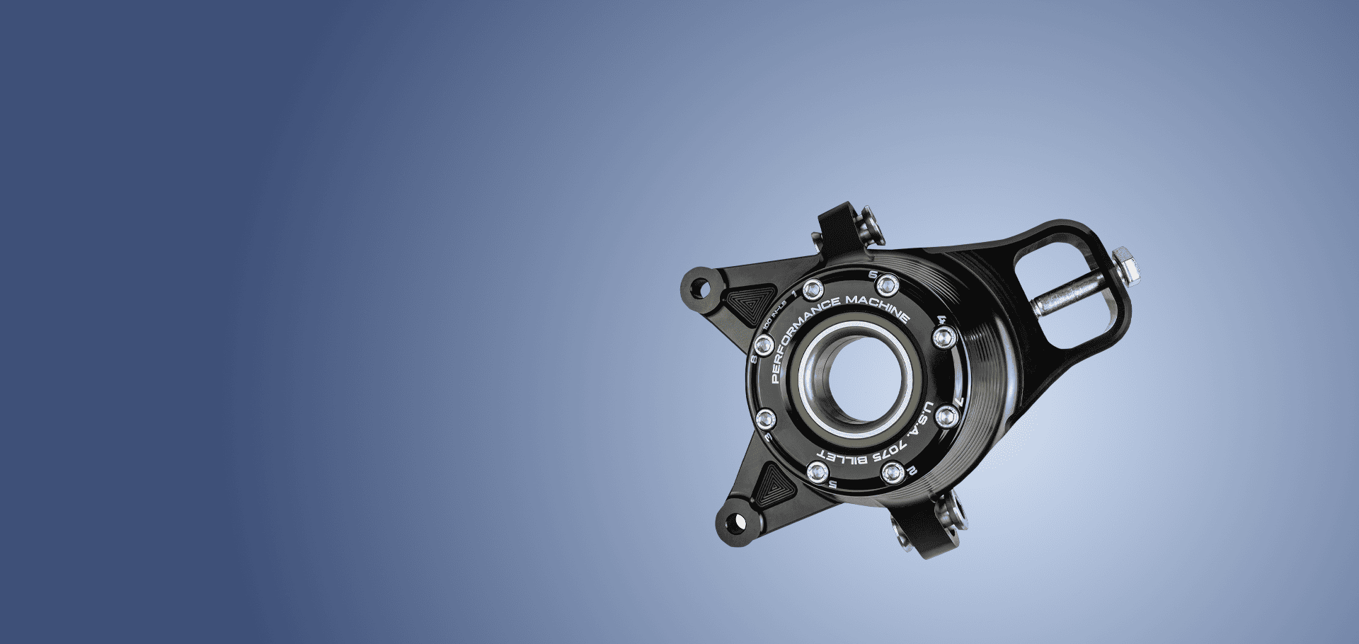
Machined Rigid Bearing Carrier

Prevent gear centerline deflection in critical differentials using high-strength iron carriers, which maintain strict dimensional tolerances under maximum operating torque.
Contact Us
Overview

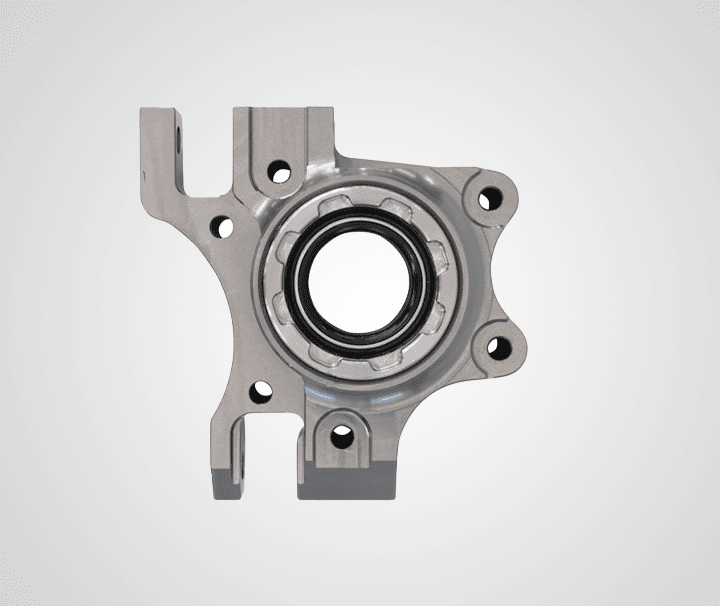
Precision Bearing Carrier Manufacturing

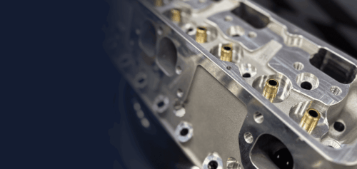
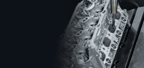
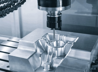
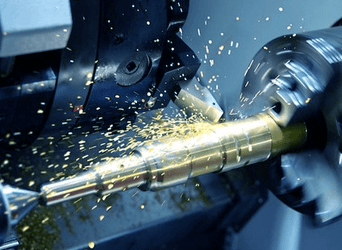
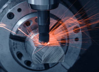
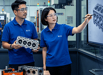
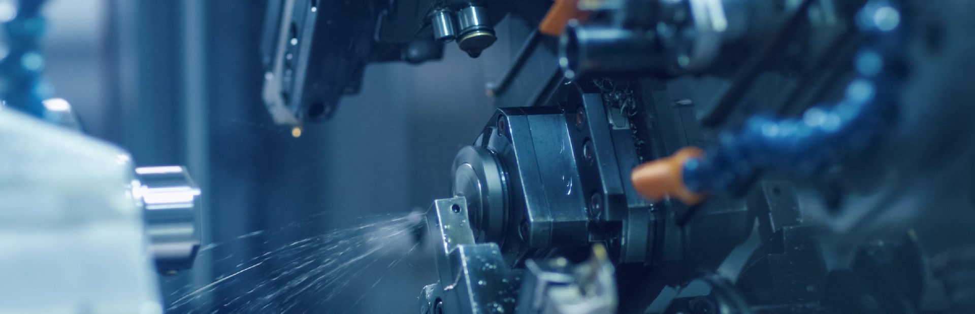
Horizontal CNC machining centers process high-density ductile iron castings, maintaining precise bearing seat cylindrical tolerances and ISO compliance to prevent critical outer ring migration or misalignment under heavy thrust loads.

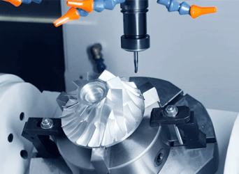
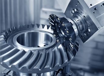
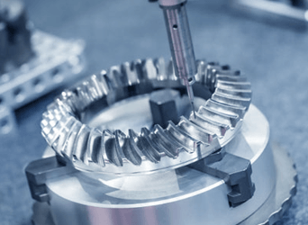
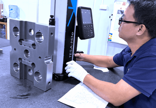
Automated multi-axis milling cells easily manage high-volume global differential programs. We complement this mass-production capacity with comprehensive verification services, providing complete coordinate measurements and ultrasonic subsurface soundness evaluation.

Contact Us
Challenge

Challenges & Solutions For Bearing Carrier

  • 01

    Bore Ovality Distortion

    We utilize custom hydraulic clamping fixtures on CNC boring mills, neutralizing structural deformation during machining to guarantee perfect cylindrical geometry after part release.

  • 02

    Axial Flange Runout

    Simultaneous face turning and bore finishing in a single component setup holds perpendicularity within twelve microns, preventing angular bearing misalignment and premature wear.

  • 03

    Internal Shrinkage Porosity

    Advanced casting simulation software guides optimal gating design and sand core venting, ensuring completely sound, dense metal structures across heavy-to-thin section transitions.

  • 04

    Bearing Ring Migration

    Precision micro-honing operations produce controlled surface micro-texture finishes inside the bore, enhancing frictional grip to prevent outer bearing rings from spinning loose.

  • 05

    Structural Flex Under Load

    Finite element modeling reinforces high-stress rib paths with high-nodularity iron chemistries, maintaining absolute gear centerline positions during sudden torque spikes.

Capabilities

Bearing Carrier Technical Specs

Our production line manufactures heavy-duty structural hub interfaces engineered to precise geometric power transmission dimensions.

Contact Us
Manufacturing Parameter Technical Specification
Material Grade EN-GJS-500-7 / EN-GJS-600-3 / ASTM A536 Ductile Iron
Bore Diameter Capacity Up to 450 mm maximum precision internal turn diameter
Seat Cylindricity Tolerance Within 0.010 mm to prevent ring distortion
Flange Perpendicularity Limit Under 0.012 mm relative to bore axis
Surface Finish Profile Between 0.8 µm and 1.6 µm (Ra finish)
Testing Verification Standard Full coordinate measuring machine (CMM) profiling
Clamping Bolt Coaxiality Within 0.040 mm of true theoretical spatial position


Why Choose Us

Why Choose Our Bearing Carrier

  • 01

    Micrometric Bore Geometry

    Horizontal boring cells hold internal diameter cylindricity within ten microns.

  • 02

    Structural Rigidity

    High-nodularity iron castings resist geometric flexing under intense thrust loads.

  • 03

    Scalable Production

    Automated machining lines deliver thousands of flawless carriers monthly.
FAQs

Frequently Asked Questions

How do you maintain exact alignment between opposing carrier bores?
We machine both internal bearing seats simultaneously using inline boring bars on dual-spindle CNC centers, keeping coaxial deviation strictly under ten microns across the housing.
Can you machine custom retention shoulders inside the carrier bore?
Yes, we deploy custom indexable contouring tools to cut precise internal thrust lips, maintaining crisp radius profiles to ensure flush bearing backing alignment during installation.
How do you handle thermal expansion differences during high-speed operation?
We calibrate our final boring dimensions to match the specific thermal coefficient of your mated housing material, preventing premature loss of bearing press-fit during operation.
What prevents thin-walled carrier shells from warping during heavy milling?
We utilize hydraulic fixture nests with programmable pressure zones, counteracting clamping forces evenly to prevent structural twisting while cutting deep external reinforcement rib geometries.
How are deep lubrication oil holes integrated into the carrier?
Our horizontal machining centers utilize high-pressure through-spindle coolant drills to plunge oil delivery passages directly into the bore walls without creating interior exit burrs.