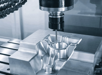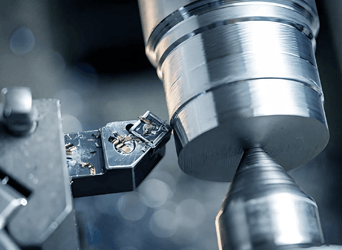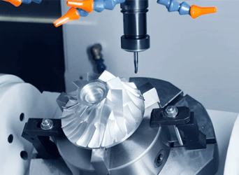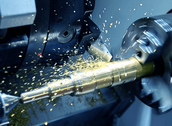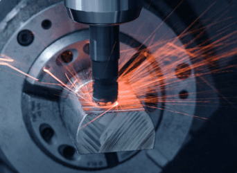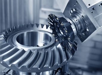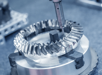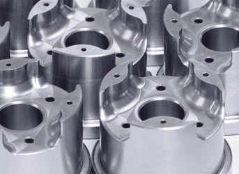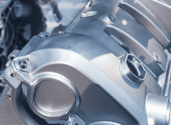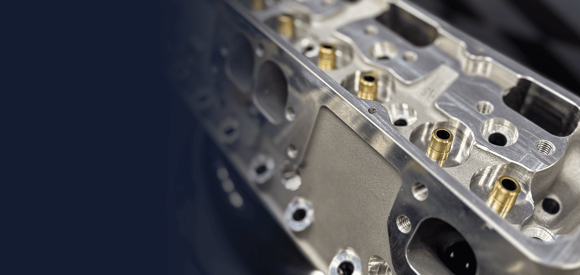
Cylinder head machining for engine programs: new heads machined from aluminum castings to your drawing for OEM and Tier programs and motorsport engineering teams.
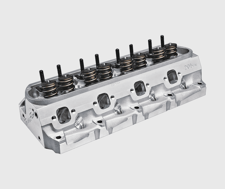
DekAutomotive machines new cylinder heads from aluminum cast blanks to OEM drawings for engine teams at OEMs, Tier suppliers and motorsport engineering teams: engineering samples, validation parts, pilot, low-volume and repeat production.
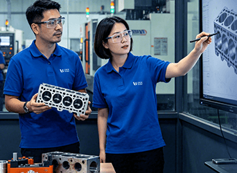
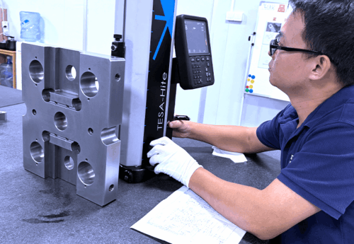
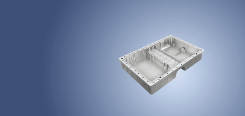
Each batch is CMM inspected and keeps its material traceability, with inspection reports on request. Heads belong to our powertrain components range, alongside motor housings for e-drive and hybrid programs; see our order process.
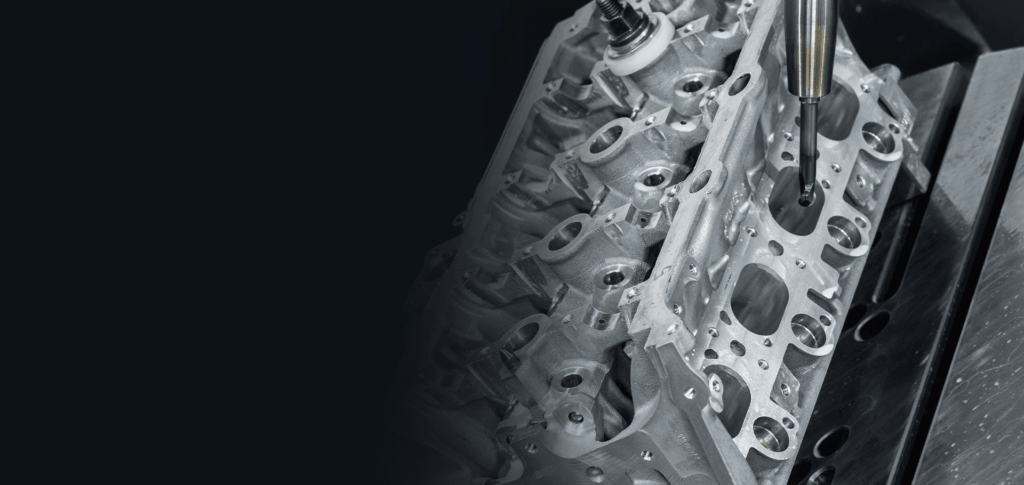
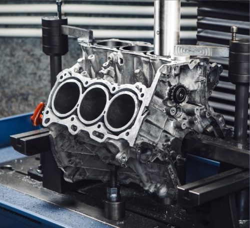
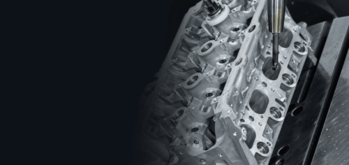
Locating pads and holes are machined on the casting first, so every later operation references the drawing datums and not the raw cast surface. Valve train, combustion chamber roof, ports and cooling circuit all locate from these datums.
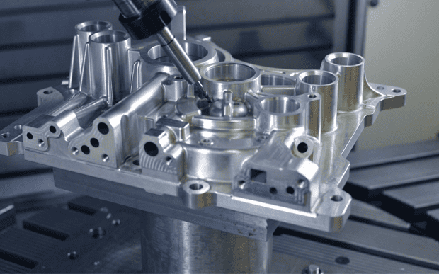
The deck face seals against the head gasket, usually an MLS gasket, and is machined flat and to the specified roughness. Its bolt pattern must agree with the engine block deck, so both parts are often quoted together.
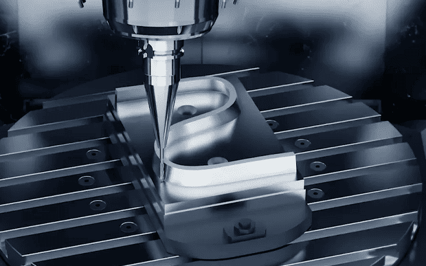
Cam caps are fitted and torqued, then the camshaft bores are line bored as one axis, so coaxiality along the camshaft axis is set in a single operation and read per ASME Y14.5 / ISO 1101.
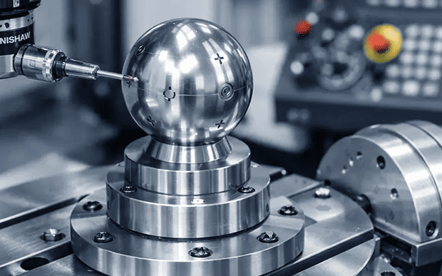
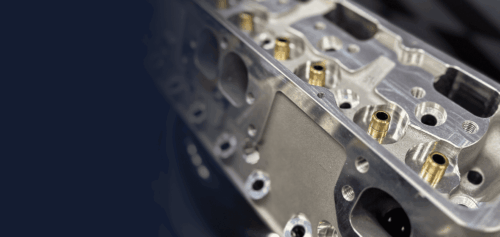
Seat insert pockets and guide bores are machined in one setup per valve, so seat-to-guide concentricity holds. Seat angle and guide bore diameter are then verified by CMM and form gauges.
Injector and spark plug bores and their sealing faces are positioned to the combustion chamber geometry; injector bore true position is checked by CMM against the combustion chamber and deck.
A356-T6 cast blanks machined to drawing: the common choice for passenger car and light engine heads, where T6 heat treatment gives strength and stable machining.
A319 cast blanks machined to drawing for heads where the casting supplier specifies a copper-bearing alloy. Porosity acceptance on machined surfaces is agreed before the first parts.
Seat insert and guide materials are customer-supplied or specified on the drawing, alongside the casting specification settled before the first parts.
The table summarizes how we machine and inspect cylinder heads; tolerances, roughness and porosity criteria come from your drawing and casting specification.
| Manufacturing Parameter | Technical Specification |
|---|---|
| Part types | New cylinder heads machined to OEM drawings |
| Materials | Aluminum A356-T6 and A319 castings |
| Blanks | Cast blanks machined to drawing |
| Critical features | Deck face, cam bores, valve seat and guide bores |
| Inspection | CMM, roughness tester, form gauges |
| Datums and GD&T | ASME Y14.5 / ISO 1101 |
| Documentation | FAI, inspection reports, MTRs, on request |
| Quantities | Engineering samples to repeat production |
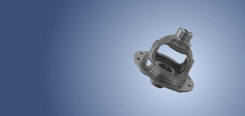
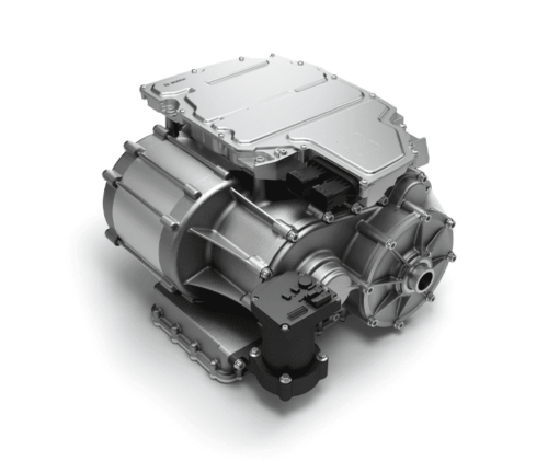
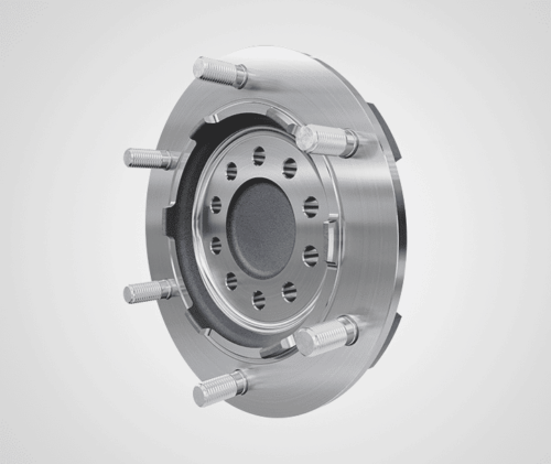
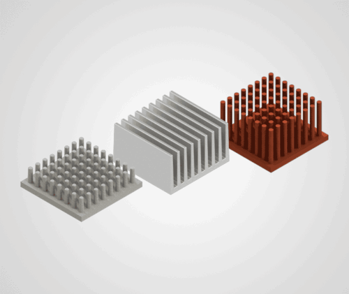
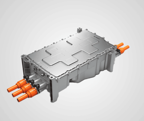
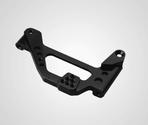
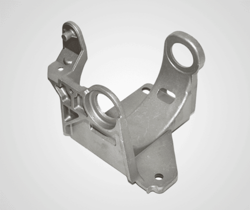

Every feature is located from the same drawing datums.

Each batch is CMM inspected, with reports on request.

Fixed route, fixtures and inspection plan once the design is frozen.
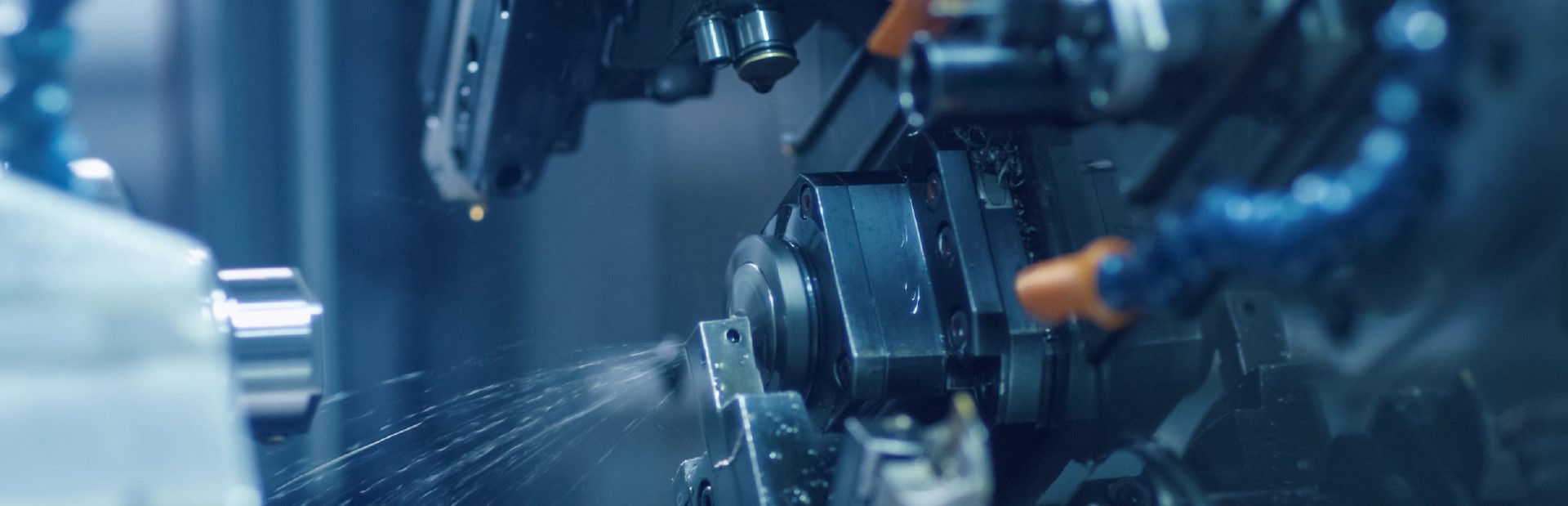
We integrate advanced machining, specialized materials, and surface finishing to deliver mission-critical parts that meet every rigorous automotive standard.
Fill out the form below and our team will get back to you promptly with a personalized quote tailored to your needs.